About
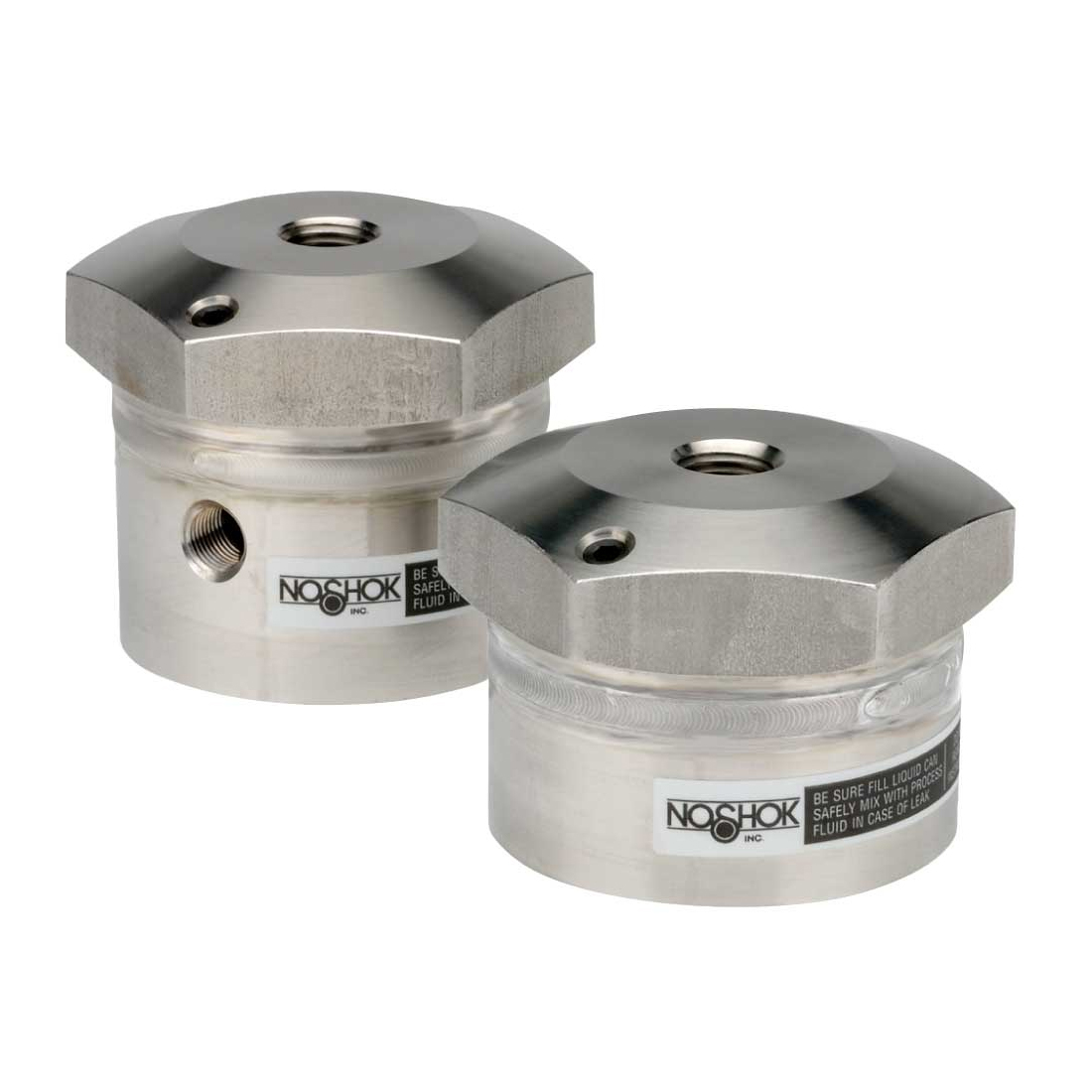
Type 29 Welded Diaphragm Seal, High Displacement, 1/4" NPT Instrument Conn, 316 Stainless Steel, 316 Stainless Steel Diaphragm, 1/4" NPT Process Conn, 316 Stainless Steel
Featured Specifications
Instrument Connection Size
1/4 in
Diaphragm Material
316 Stainless Steel
Process Connection
1/4" National Pipe Thread (NPT)
Assets
 Dimensions
 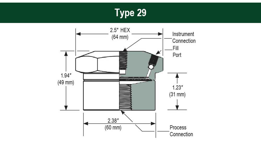 Dimensions
  Data Sheet
Product Specifications|Instruments|O-Ring Temperature Limits|Diaphragm Pressure and Temperature Limits|Bottom Housing Material Maximum Pressure and Temperature Limits|Additional Information|Options and Accessories|Applications|Limitations Which Apply Are|Prop 65 Warnings
Product Specifications
▲| Type | Diaphragm Seal |
| Style | Non-Replaceable Diaphragm Seal |
| Instrument Connection | 1/4" National Pipe Thread (NPT) |
| Upper Housing Material | 316 Stainless Steel |
| Diaphragm Material | 316 Stainless Steel |
| Process Connection | 1/4" National Pipe Thread (NPT) |
| Seal Type | Threaded with welded diaphragm |
| Lower Housing Connection Size |
|
| Lower Housing Connection Type | National Pipe Thread (NPT) |
| Lower Housing Flushing Port | Optional 1/8" NPT and 1/4" NPT |
| Upper Housing Type | Continuous Duty |
| Diaphragm Size | 2.1 in |
| Diaphragm Displacement | 1.5 mL |
| Warranty | 1 yr |
Instruments
▲| Instrument Type | Gauges, Transducers, Switches |
O-Ring Temperature Limits
▲| O-Ring Temperature Limits for Nitrile Butadiene Rubber (NBR) Material ºF | -40 to 250 ºF |
| O-Ring Temperature Limits for Polytetrafluoroethylene (PTFE) Material ºF | -400 to 400 ºF |
| O-Ring Temperature Limits for Fluorocarbon (FKM) Material ºF | -10 to 400 ºF |
Diaphragm Pressure and Temperature Limits
▲| Diaphragm Pressure Limits for Polytetrafluoroethylene (PTFE) Material | 2,000 psi |
| Diaphragm Pressure Limits for Fluorocarbon (FKM) Material | 2,000 psi |
| Diaphragm Temperature Limits for Polytetrafluoroethylene (PTFE) Material ºF | -40 to 400 ºF |
| Diaphragm Temperature Limits for Fluorocarbon (FKM) Material ºF | -10 to 400 ºF |
| Note for Diaphragm Pressure and Temperature Limits | Metallic diaphragms determined by pressure range of seal type, restricted to temperature range of fill fluid. |
Bottom Housing Material Maximum Pressure and Temperature Limits
▲| Maximum Pressure Limits for Glass Transition Temperature (Tg), Tetoron Cotton (TC) Bottom Housing Material | 200 psi |
| Maximum Pressure Limits for Polyvinylidene Fluoride (PVDF) Bottom Housing Material | 200 psi |
| Maximum Pressure Limits for Polyvinyl Chloride (PVC) Bottom Housing Material |
|
| Maximum Pressure Limits for Polypropylene (PP) Bottom Housing Material | 200 psi |
| Maximum Temperature Limits for Glass Transition Temperature (Tg), Tetoron Cotton (TC) Bottom Housing Material ºF | 150 ºF |
| Maximum Temperature Limits for Polyvinylidene Fluoride (PVDF) Bottom Housing Material ºF | 180 ºF |
| Maximum Temperature Limits for Polyvinyl Chloride (PVC) Bottom Housing Material ºF |
|
| Maximum Temperature Limits for Polypropylene (PP) Bottom Housing Material ºF | 140 ºF |
| Note for Maximum Pressure and Temperature Limits Bottom Housing Material | Metallic lower housings determined by pressure range of seal type, restricted to temperature range of fill fluid. |
Additional Information
▲| Additional Information |
|
Options and Accessories
▲| Cooling Elements |
|
| Diaphragm Seal Fill Options |
|
| Distribution Manifolds | NOSHOK's Distribution Manifolds connect multiple instruments to one diaphragm seal, eliminating multiple connections that lead to possible leak paths. |
| Plain and Armored Capillaries |
|
Applications
▲| Application |
|
Limitations Which Apply Are
▲| Limitations Which Apply Are | These units must be operated within the catalogued environmental and application parameters. Determination of failure will be made by NOSHOK, Inc.'s equipment and personnel or a certified test facility specializing in this type of evaluation. Gauge failures determined to be caused by over-range, incompatibility with environment or product media and abuse will not be considered under this warranty. NOSHOK, Inc. will, at its discretion, repair or replace the working parts of the damaged gauge without cost to the customer. In keeping with and for purposes of product and/or manufacturing process improvements, NOSHOK, Inc. reserves the right to make design changes without prior notice. |
Prop 65 Warnings
▲| Prop 65 Warnings | ⚠️ WARNING: This product can expose you to chemicals including Nickel, which is known to the State of California to cause cancer. For more information go to www.P65Warnings.ca.gov |